Hanns.G HN Series User Manual Page 21
- Page / 21
- Table of contents
- BOOKMARKS
- 19 inch HN Series 1
- TFT LCD Monitor 1
- Recycling Information 4
- TABLE OF CONTENTS 5
- SAFETY NOTICE 6
- FEATURES 8
- INSTALLATION INSTRUCTIONS 9
- CONTROLS AND CONNECTORS 11
- ADJUSTING THE VIEWING ANGLE 12
- OPERATING INSTRUCTIONS 13
- FRONT PANEL CONTROL 14
- HOW TO ADJUST A SETTING 15
- PLUG AND PLAY 16
- TECHNICAL SUPPORT (FAQ) 18
- APPENDIX 20
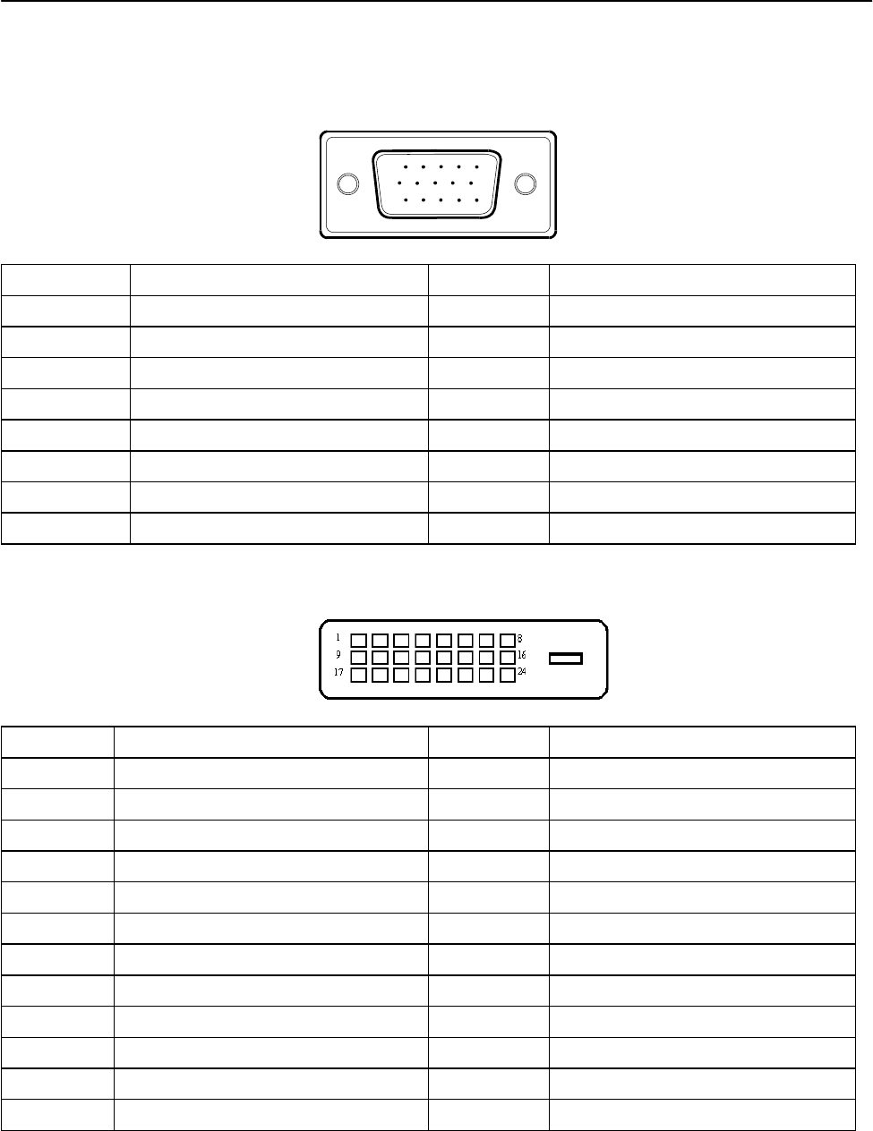
- CONNECTOR PIN ASSIGNMENT 21
Related products and manuals for TVs & monitors Hanns.G HN Series
 (22 pages)
 (21 pages)
(22 pages)
(23 pages)
(15 pages)
(23 pages)
(23 pages)
(21 pages)
(21 pages)
(22 pages)
(23 pages)
(15 pages)
(23 pages)
(23 pages)
 (28 pages) (22 pages)
© 2020, manymanuals.com. All rights reserved. | 3.759 s |
 Manymanuals.com
 Manymanuals.de
 Manymanuals.fr
 Manymanuals.it
 Manymanuals.pl
 Manymanuals.cz
 Manymanuals.es
 Manymanuals-pt.com
Comments to this Manuals